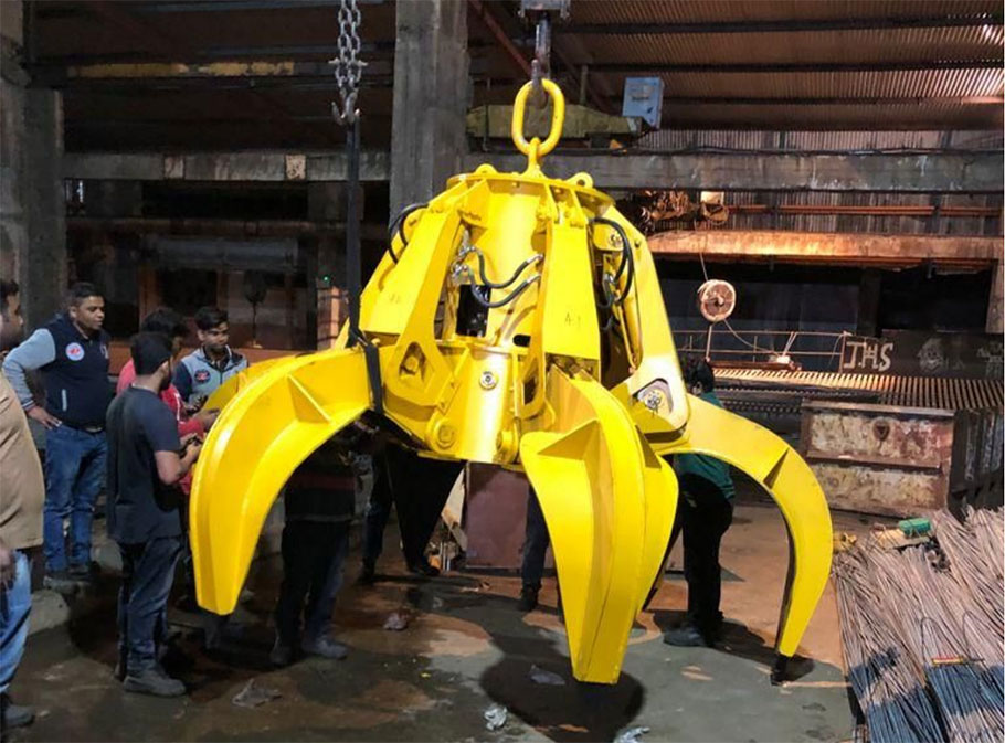
Hydraulic grab bucket is an effective tool that can replace manpower for loading and unloading bulk cargo such as mineral powder, fertilizer, grain, and coal in various harsh environments. The crane grab has its own hydraulic system, and the main components of the hydraulic system adopt international famous brand products, which makes the grab have excellent performance.

Crane Grab work:
The supporting crane is equipped with a cable reel and lowered to the grab. Our grab provides cable plug and socket connections. The hydraulic center of the grab (motor, oil pump, control valve block, etc.) is installed in the center of the grab. In the body, another grab bucket electric control cabinet (placed in the driver's cab) is made, and the operation switch is installed on the operator's cab console. The grab bucket determines the volume, motor power, self-weight and other parameters of the grab bucket according to the total lifting capacity of the crane and the materials to be grasped, and determines the connection method according to the crane.
Overview of how crane grab works
The work of the grab bucket is divided into two parts: the motor rotates clockwise and the motor rotates counterclockwise.
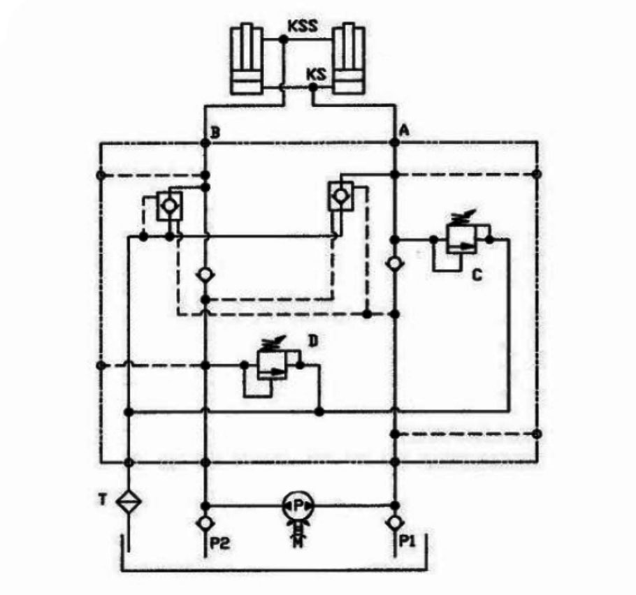
The grab motor rotates clockwise, and the hydraulic pump starts to send hydraulic oil from the oil tank to the pressure line P1 through the check valve. The hydraulic oil passes through the check valve, the main relief valve and the pipeline A to the KS on both sides of the hydraulic cylinder piston. When the hydraulic cylinder is extended, the return oil returns to the oil tank through the pipeline B through the hydraulic control check valve, the return oil pipe and the filter T. Correct adjustment of the hydraulic check valve cushioning prevents the grab from "chattering". The main relief valve can be unloaded under low pressure, and ensure that the pressure at the piston end of the cylinder is always at the set value, thereby preventing the grab from opening abnormally when the power is cut off; it can also prevent the hydraulic oil in the tank from heating up too quickly. At this time, the pressure measuring hose and pressure gauge can be connected to the pressure measuring joint in the upper pipeline to detect the working pressure when the hydraulic pipeline is closed. The grab motor rotates counterclockwise, and the hydraulic pump sends the hydraulic oil from the oil tank to the pressure line P2 through the one-way valve. Via the check valve and line B, the hydraulic oil is sent to the KSS on both sides of the piston rod of the hydraulic cylinder. When the hydraulic cylinder is recovered, the return oil is returned to the oil tank through the pipeline A, through the hydraulic control check valve, the relief valve, the oil return pipe and the filter F. At this time, the pressure measuring hose and pressure gauge can be connected to the pressure measuring joint in the lower pipeline to detect the working pressure when the hydraulic pipeline is opened.
